Why Do Supports Tear Chunks Out of Resin Prints After UV Curing?
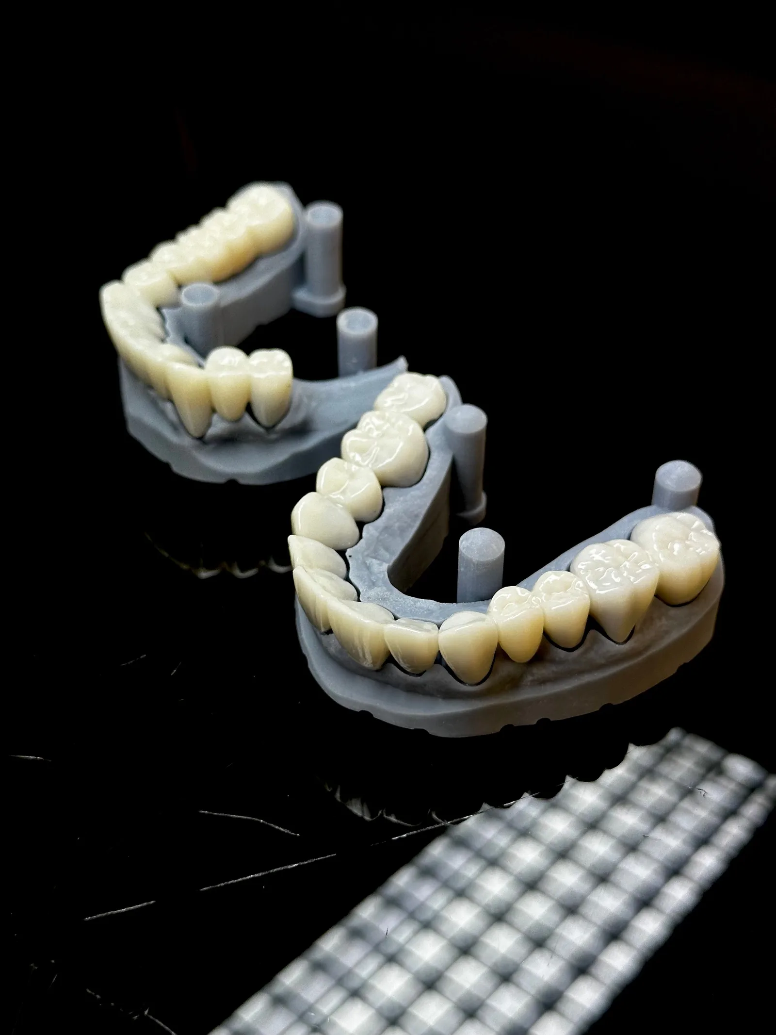
One of the classic problems with SLA and MSLA printing: the print looks fine straight off the machine, but as soon as you start removing supports, chunks of material tear out of the part itself. This is especially noticeable after UV post-curing — the surface becomes more brittle, and the force needed to remove a support is now enough to snap or tear the layer it’s attached to.
At first glance, most people blame the support. In practice, it’s usually a combination of factors: wrong model orientation, supports that are too large or too rigid, too large a contact point, overexposure, the wrong support density, or UV curing that’s too long or too intense.
The right fix is rarely just “use weaker supports.” The goal is that the support reliably holds the model during printing, while causing the least possible damage on removal.
How does the support system work on SLA and MSLA printers?
On SLA/MSLA printers, the model doesn’t simply “float” — the support structure generated by the slicer is what keeps it connected to the build plate or support platform. (For more on how the two most common 3D printing technologies work, see our earlier article: How Does a 3D Printer Work? FDM and MSLA Explained.)
A support is typically made up of several parts:
- a raft or base, which attaches to the build plate,
- a trunk, which mechanically holds the model,
- branches, which distribute the load,
- a contact point or tip, which connects directly to the model.
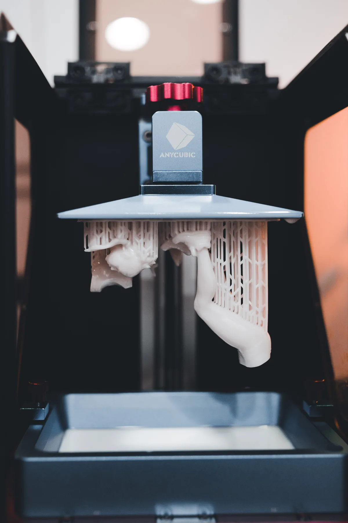
The critical part is that last connection. The support needs to be strong enough there to survive printing without detaching, but not indiscriminately oversized. Every layer during printing can produce separation forces — if orientation or support structure causes these to concentrate in one spot, significant local stress builds up between the support and the model.
That’s why the “the stronger the support, the better” approach is wrong.
Why does an overly strong support tear the part?
A support can actually work as a controlled breaking point. Ideally, on removal, it’s the connection between support and model that separates — not the model itself.
But if the contact point is too large or the support too rigid, the resistance of that connection can exceed the local strength of the part. Three things can happen on removal:
- the support detaches from the model — the ideal outcome;
- part of the support snaps off, leaving a small stub on the model;
- the model’s own surface gets damaged or torn.
The third case typically shows up when the support tip is too large, connects too deep into the surface, or the resin has become significantly more brittle from post-curing.
An oversized support tip is one of the most common causes
The size of a support’s contact point directly determines how much force is needed to remove it. A larger tip provides more grip, is more stable during printing, and is less prone to snapping off — but it can also cause more surface damage, which is especially problematic on visible surfaces where the support lands directly on a cosmetic area.
In that case, the right move isn’t simply setting every support smaller across the board. A better solution is often relocating supports to areas where marks, surface irregularities, or post-processing are less of a concern.
Good support setup is partly a geometry question, not purely a slicer-settings question.
When do you need strong supports, and when is “more, smaller” better?
This is one of the most important practical decisions.
Stronger supports make sense when a lot of mass hangs from the support, there’s a large cross-section above the support, a long or slender feature is building upward, large separation forces are expected, or the model’s orientation causes a large area to release from the FEP film all at once.
More, smaller supports can be better when the model’s surface is thin or fragile, there are many small overhangs, fine surface detail needs to be preserved, the goal is minimal support marking, or the load can be distributed across several points.
The key is load distribution. A single very thick support is often trying to do the same job that several smaller, well-placed supports can do more stably and with less surface damage.
Model orientation often matters more than support settings themselves
Many support problems are actually orientation problems. Say you’re trying to print a large, nearly horizontal surface. If the part is almost parallel to the build plate, a large area can release on a single layer during separation — which can mean higher separation force, higher support load, support failure, layer delamination, deformation, or ultimately the model tearing away from its supports.
A slight change in orientation, however, can reduce the cross-section per layer. This often significantly improves print stability.
It’s worth optimizing the model’s orientation first, and only maximizing support afterward.
Overexposure can also cause the problem
One common source of resin printing defects is exposure set too high. If exposure is too aggressive, the resin cures beyond the intended area — this doesn’t just hurt detail, it can also make the connection between supports and model more robust and rigid than intended. The result can be thicker support connections, harder support removal, loss of detail, narrowing of small holes or gaps, and a higher risk of damage.
The correct exposure time depends on the printer, LCD, resin, layer thickness, and other parameters, so there’s no universal “right” value. Don’t increase exposure just to make supports hold more securely. Supports should be stabilized primarily through geometry and proper slicer settings.
What happens during UV post-curing?
A freshly printed resin part has already solidified by the time it comes off the printer, but the polymerization process — and the material’s final properties — continue to change during post-curing.
Proper UV post-curing generally increases stiffness and final strength, but depending on the specific resin and curing parameters, the part can also become more brittle. This matters at the exact moment of support removal: a freshly washed, less-cured part can behave more flexibly in some cases, while the same part after intensive UV curing is less able to absorb the local deformation caused by removal.
The result can be that instead of the support connection breaking in a controlled way, the model’s surface cracks or chips. That’s why it’s not always advisable to remove supports after maximum post-curing.
The actual optimal sequence depends on the resin and manufacturer, so the material’s own manufacturer guidance always takes priority. As a general principle, though, it’s worth understanding: printing, washing, support removal, and UV post-curing are interdependent process steps.
How should you set up the support system on a resin printer?
Good SLA support setup doesn’t come down to a single parameter. It’s worth thinking of it as a system.
1. Optimize orientation first. Check how the cross-section changes layer by layer — the goal is building up large cross-sections gradually, avoiding critical surfaces, reducing separation forces, and minimizing the amount of support needed.
2. Support the main load-bearing points. Not every point needs the same kind of support: use stronger support on higher-load areas, while lighter support is often enough for fine details.
3. Don’t put supports on the most visible surface. Support marking is always a trade-off. With the right orientation, supports can be placed on surfaces that can be sanded later, aren’t seen by the end user, or aren’t functionally critical.
4. Check the contact point. If supports are stable but tear the surface on removal, the contact geometry is the first thing worth reviewing. The goal isn’t the largest possible connection, but the minimum connection that’s reliable for printing.
5. Reduce the number of supports, but not blindly. Too few supports can cause print failures; too many increase post-processing, cause more surface defects, and make the whole support structure more rigid. Good setup means necessary support, not maximum support.
Quick troubleshooting checklist
If supports keep tearing the part, it’s worth working through the problem in this order:
- Model orientation — Is there too large a horizontal cross-section? Is there a simpler orientation?
- Support placement — Did supports land on a critical or thin surface?
- Tip size — Is the contact point unnecessarily large?
- Support distribution — Could several smaller supports replace one large one?
- Exposure — Is it too high for this resin and layer thickness?
- Post-curing — Is the UV treatment too intense or too long?
- Material choice — Do the resin’s mechanical properties actually match what the part is used for?
That last point matters more than it might seem. A visual model and a mechanically loaded prototype don’t necessarily call for the same resin.
How to design a resin prototype for manufacturability
For resin prototypes, manufacturability is worth considering as early as the CAD geometry stage. If you know a surface will carry a support, it’s worth asking: does this surface really need this orientation, can a less sensitive support zone be designed in, is there enough material to clean up the support mark, which surfaces are functional, where is a surface deviation acceptable, and where does geometric accuracy matter more than an invisible support mark.
This goes beyond the classic “which support settings should I use?” question. A well-manufacturable resin part isn’t just a CAD model the slicer can somehow print. Geometry, orientation, supports, material, post-curing, and post-processing all need to be managed together.
We applied exactly this thinking on the MSLA printing of the Sztárbox championship belt emblem: given the laurel wreath’s fine, curved detail, we decided during the design phase which surfaces to split into separately printed parts, so support marks would land on areas that could be sanded or painted over afterward — not on the visible, close-up-camera-ready surfaces.
When is it worth bringing in a specialist?
If support tear-out keeps recurring across multiple models on the same printer, it’s worth examining the whole process as a system rather than tweaking a single support parameter. That’s especially true when the print is a business or functional prototype, multiple identical parts need to be produced, reproducible quality matters, post-processing is part of the production chain, or the part has real mechanical requirements to meet.
In these cases, jointly optimizing model orientation, support strategy, resin, exposure, and post-curing usually delivers more than continuously raising a single slicer parameter.
At BWE Mechanical Design, that’s why industrial and low-volume additive manufacturing isn’t just about the printing step — it’s about the whole production process, from CAD geometry and orientation through support strategy to printing and post-processing. Our industrial and low-volume 3D printing service is built around exactly this integrated approach.
Summary
If a support tears a chunk out of your part after UV curing, the support itself isn’t necessarily “too weak” or “too strong” on its own. The real cause is usually a combination of orientation + support geometry + exposure + post-curing. The goal is for the support to be rigid enough to hold the model reliably during printing, but to release in the intended place on removal — without damaging the part. If you’re dealing with recurring support problems on a functional or business-critical resin print, request a quote for our parts manufacturing service — our engineering team can help optimize model orientation, support strategy, and the whole production process together.
Related Articles
Planning a Similar Project?
Send us your model or drawing — free consultation, with personalized quotes within 24 hours.